How to use a hybrid method of CFD analysis for product optimization and performance improvement while reducing the computational effort and the time required to achieve the results
ABSTRACT
CAE is highly effective for product optimization. In this technical article, we describe how a hybrid method of computational fluid dynamics analysis was used to enhance the design of a medical device to improve its ability to maintain a stable microclimate around a patient, but also to reduce both the computational efforts and the time required to obtain these results. A microclimate requires the maintenance of specific values of temperature, humidity and air velocity around a patient.
In open devices, this is usually generated and sustained by means of three humidified heated air jets positioned one on either side and one at the foot of the bed.
The design parameters of this set-up form an optimization problem where the sum of the relative deviations of temperature and humidity has to be minimised at the patient’s mid-region, while air velocity has to be constrained to less than 0.35 m/s and heat loss through the ceiling towards the room has to be contained.
In this CFD consulting study, the hybrid method was adopted of using ANSYS CFX to calculate the flow field, and modeFRONTIER to automate the design process and to drive the computation chain toward the identification of an optimal solution.
FURTHER REDUCTION OF THE HEAT LOSS COMPARED TO THE BEST DESIGN OF THE NSGA-II FIRST PHASE DESIGN OPTIMIZATION: A FURTHER 4% GAINED 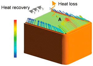
The present work describes an advanced technique to improve the results of a multi - objective optimization by using advanced technologies, such as modeFRONTIER’s Self Organizing Maps (SOM) and Response Surface Models (RSM), to drive the analyses into the desired direction with few additional computations. In many real-life engineering challenges, such as the one here described, there is a large number of input parameters spanning a high dimensional space, and design evaluations are performed with computationally-expensive numerical model runs. Hence, the need is to reduce as much as possible the design variants needed by the optimizer to find the desired improvements. This paper suggests an innovative procedure applied to the flow field optimization of a medical device.
CFD Model and optimization details
The objective of the current study is to optimize the design of a medical device used to maintain a stable microclimate around the patient. In open devices, such as the subject of this paper, the microclimate can be achieved by a special arrangement of humidified heated air jets: figure 1 shows a schematic setup, with the bed surface with three nozzles forming the above mentioned jets, one at each lateral side and one at the foot side of the device. Heat and moist recovery is done by recirculation, fed by suction at the head side of the device (not shown here): such recovery should me maximized, in order to reduce the heat loss. Microclimate comprises specific values of temperature, humidity and velocity around the patient: as usual in literature, the reference location is assumed at the center of the patient’s body, further denoted as point A (see Figure 1). Such outputs are mainly influenced by the flow field, which is induced by the air jets of the nozzles. Hence, the design parameters of the air jets, such as velocity distribution, velocity angle, temperature and humidity, form an optimization problem.
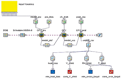
The sum of relative deviations of temperature (T) and humidity (h%) at point A was set as one objective to be minimized: target = (|T_A − T_target| / T_target) + (|h%_A − h%_target| / h%_target) Additionally, it should be less than 0.025 (2.5%). Air velocity at point A, has been constrained to be less than 0.35 m/s. The second objective is related to the heat loss index: the difference between the enthalpy of the inlet air jets and the air leaving the model domain through the ceiling towards the room shall be minimized. A total of ten input variables were used to parameterize the warm air flow. In particular, a first set of variables are related to the velocity magnitude of the size and foot air jets, an other set to their orientation and profile, while the latter two parameters were their temperature and humidity. An efficient technique to model the flow field and its dependencies from design parameters is computational fluid dynamics (CFD). The computational domain comprises the space around the patient and a cube forming the environment around the device (the room). At the exit areas of the nozzles, inlet boundary conditions (BC) with suitable velocity profiles, temperature and humidity distributions were specified and linked to the values of the input variables. An outlet BC was specified at the suction louver, while the device solid surfaces and lateral boundaries were modeled as adiabatic walls. The room ceiling was specified as an opening BC (pressure=1atm and temperature=20°C) in order to account for heat and air loss due to buoyancy. A tetrahedral mesh was generated for the computational domain, and Reynolds Averaged Navier-Stokes (RANS) computations were carried out. In this study ANSYS CFX is applied to calculate the flow field, while modeFRONTIER is used to automate the design process and drive the computational chain towards an optimal solution. The process has been set up into the modeFRONTIER environment, and it is represented by the workflow chart of figure 2.
Optimization strategy
First, a direct optimization with a Multi Objective Genetic Algorithm (namely, NSGA-II) allowed the designer to explore the wide range of possible solutions. For some reasons, the results were not fully satisfactory: namely, the comfort (target objective) has been over-optimized respect to the heat loss. For time constraint reasons, only a few extra computations were still available, so an advanced strategy was set up. The proposed approach is aimed to quickly reach a desired zone of the Pareto Set that was not mapped by the initial optimization. First an application of SOM techniques has been used to detect local correlations, and hence to circumscribe the scope of the search in the input variables’ space, “reducing” the problem. After the definition of new bounds for the input variables, a new Design of Experiment (DOE) campaign was set up and evaluated through CFD model runs, and the new data has then been interpolated with Response Surface Modeling (RSM) techniques. Finally, an almost instantaneous run of the Genetic Algorithm has been applied to these meta-models, and the most promising forecasts were validated by means of new CFD simulations, delivering the final result to the designer.
Apart from the improvements obtained with regard to the initial design, this kind of hybrid methods guarantee a reduction of the computational efforts needed to obtain such results, compared to a full direct optimization. In particular, the usage of SOM techniques allows the designer to select the most promising area for the objectives of his search. This technology brings two major advantages to such kind of applications. First, it becomes even more time-saving and convenient with regard to other approaches while the dimension of the input variables’ space increases. Secondly, the process of bounds focusing takes advantage not only of the computed solutions, but also of the estimation of the probability density of the solution space.
Initial NSGA-II run
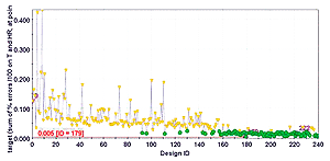
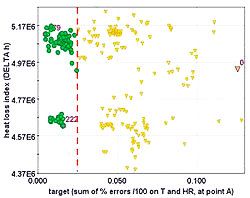
Initially, the bounds of the 10 independent input variables were quite wide, in order to map the space of the possible solutions in an exhaustive way. With such setup, a multi-objective NSGA- II algorithm has been used to drive the CFD code in exploring new designs. The initial population of 20 designs has been obtained adding a Random DOE (Design Of Experiments) sequence to the original design. The genetic algorithm has been run for 15 generations, with a crossover probability of 0.9 and a mutation probability of 1.0. All constraints have been considered as penalty functions for the assigned objectives. Figure 3 shows the evolution of the target objective value during the optimization. Figure 4 depicts the scatter chart of the explored configurations in the two objectives (target and heat loss) plane. In this first phase of the optimization, the algorithm was able to exit the unfeasible region it started from (the initial population could not achieve the assigned constraint on target).
Figure 4 highlights also that the algorithm focused on two main regions of feasible solutions, and tended to over - optimize the values of humidity and temperature, while the heat loss was not improved sufficiently. In fact, the cloud of feasible points at the bottom of figure 4 has still an appreciable margin from the limit assigned to the deviation from the ideal climate control performance (target less than 0.025). Since target and heat loss seem to be opposing goals, it can be expected to find some configurations able to improve further the heat loss by staying more tight to the constraint assigned to target. The idea is to search for them in the most efficient way, exploiting the data already available after the optimization step with NSGA-II, plus few other well-targeted CFD simulations. To this purpose, a virtual optimization applying a hybrid SOM-RSM strategy is proposed here. An advantage of this approach compared to a longer direct optimization (apart from the reduced number of additional simulations needed to find the desired solutions) is a more thorough understanding of the local correlations between parameters and optimization goals. This becomes even more clear when increasing the number of variables and responses involved.
Combined SOM and RSM strategy
The Self-Organizing Map (SOM) is an algorithm that projects high dimensional data onto a two-dimensional map. The projection preserves the topology of the data so that similar data items will be mapped to nearby locations on the map.
In the proposed approach, the SOM has been used to analyze local correlations between the two objectives (target and heat loss index) exploiting the results of the previous NSGA-II optimization. In fact, detecting such local correlations allows to identify a reduced input parameter range that includes the most promising designs for the desired output values. In this way, a subsequent search campaign could be set up within this reduced input parameter space.
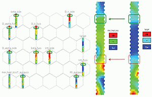
Figure 5 displays the component charts relative to the built SOM. The grid on the left collects the whole set of SOM component charts, and in particular also the design parameters. At the right, the component charts of target and heat loss index are shown in detail. In such conventional charts, each hexagon is a “box” containing a group of similar designs, previously computed by the CFD model or interpolated by the SOM’s unsupervised neural network. They are “similar” with respect to the complete vector of parameters and output values, which define them in the n-dimensional space. Adjacent hexagons mean similar groups. A corresponding hexagon in 2 different parameter’s maps (i.e. an input and an output one) represents the same “box”, hence including the same set of designs. The hexagon’s color, conversely, depends on the map itself: it represents the averaged value of such parameter within the selected group of designs included in the “box”. Comparing the color pattern of a corresponding set of hexagons in two different maps, means looking for a set of designs with a certain common trend of parameters (local correlation between the parameters).
Therefore, local correlations between a couple of parameters can be detected comparing their SOM maps and searching for zones where hexagons have similar color patterns. Since the goal here is to check whether a local correlation exists between the heat loss and a target value slightly less than 0.025, their SOM charts are compared in Figure 5 (right). A local correlation of the two outputs, where target is a bit lower than 0.025 (pale blue color), exists in the SOM units underlined with a solid line in Figure 5 top-right, as the similar uniform color pattern testifies. As an example, no local correlation can be assessed for the design groups in the dotted line square, (Figure 5 bottom-right): the corresponding target and heat loss color patterns are not similar.
After selecting the hexagons included in the solid line box in the right side of Fig.5, a re-definition of the design space has been achieved by restricting the design parameter to the range defined by the designs included in such SOM units (represented by the range of colors of the corresponding hexagons in the left side of Fig.5, the green-framed ones). Each one of the input variable ranges has been reduced sensibly, in most of the cases more than halved, with an average reduction of 43%: this means that the size of the search domain is strongly reduced and focused only to the most promising zones with regards to the designer’s requirements. This leads to a much faster second step optimization. A Reduced Factorial DOE sequence of 16 configurations has been set up, in order to add uniformly few new points in such restricted input parameter space. All the previously simulated designs belonging to the selected SOM units, and hence falling within the restricted range, were added to the Reduced Factorial DOE result database. Then a RSM, namely a set of Radial Basis Functions (RBF), were trained with that data, in order to model each of the problem’s goals. Such RSMs have then been used to interpolate new configurations, disconnecting the link between the optimizer and the computationally expensive CFD calculations. In fact, upon such RSMs, a new extensive NSGA-II optimization has been performed in order to search for optimum(s) with reduced heat loss values, respecting the constraint target. In this way, approximately 1800 points were estimated in a few seconds. The results have then been filtered according to the dominance criteria, and the most promising design candidates were selected to be validated with new CFD simulations. This choice was done taking into account not only the estimated values of the goals, but also the distance of such points with respect to the training set points in the 10-dimensional parameter space. Three designs have been selected and subsequently validated with new CFD simulations.


